 En
En
 Es
Es
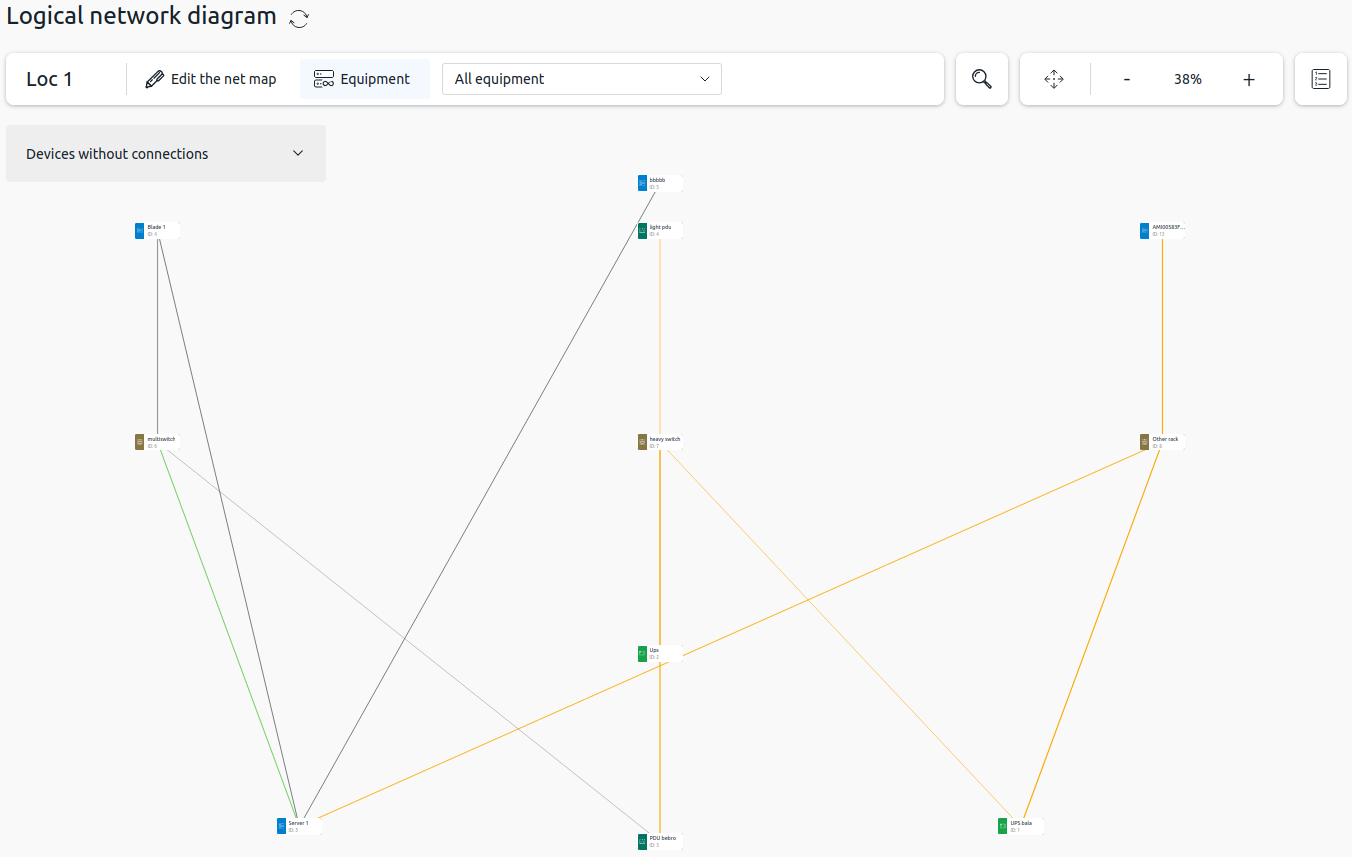
The network diagram is a graphical representation of the local network infrastructure of a data center. It shows the logical topology: connections between servers, switches, storage systems, and power equipment. It allows you, for example:
- to view information about connections between equipment at the location;
- to view information about servers and switches with a specific VLAN to check the connectivity of equipment at the location.
Module Installation
To install the module "Network diagram", click  in the right menu → Modules → go to the module card Network diagram → Install.
Working with the Network diagram
To open the Network diagram module interface, click Network diagram in the left menu. The module interface opens in view mode. If equipment with connections has been added to the location, it will appear on the map.
Legend
Equipment types and connections are shown using symbols. To view the legend, click the  button on the toolbar.
Zooming and Panning the View Area
You can pan the view by dragging and zoom the map using the  and
and  buttons on the toolbar. To fit the entire map to the screen, click the
  button.
To focus the view on a specific piece of equipment:
- Click the
 button on the toolbar.
 - In the dropdown list, select a search criterion:
- Name;
- ID.
- Enter the equipment name or ID.
- Click the equipment card in the search window.
The view will zoom in to the selected equipment.
Viewing equipment information
To display a window with information about a piece of equipment, click on it. The window shows:
- name, type and ID of the device;
- location information in a rack or chassis;
- connections grouped by status and equipment types;
- IP addresses.
To open the device card, click its name in the window title.
Viewing equipment without connections
When generating the network diagram, only equipment with connections is added to it. To add devices that have no connections, click Devices without connections. A window opens with a search bar and equipment categories:
- servers;
- storage chassis;
- PDU;
- UPS.
Devices are added to the map one by one. You can select a device to add to the map in two ways:
- by searching among all equipment of a specific type;
- by searching by device name or ID.
To see a list of all equipment without connections at the location, click the dropdown list of the required equipment type.
To use the search:
- In the dropdown list to the right of the search bar, select a search criterion:
- Name;
- ID.
- Enter the equipment name or ID. The window will only show equipment matching the criterion.
Click the required piece of equipment to display it on the map.
Equipment display filters
To filter equipment, click the filter selection field and select one of the options:
- All equipment — displays all equipment at the location. This option is selected by default;
- Network — displays connections to switches. If this option is selected, a field appears on the right where you can select a switch to display on the map. By default, All is selected — in this case, all switches and connections between them are shown;
- VLAN — displays equipment that belongs to a specific VLAN. If this option is selected, a field appears on the right where you can select a VLAN to display on the map;
- BMC — displays all equipment at the location that is connected to BMC servers;
- Power equipment — displays the location's PDUs and UPSs and all equipment that has management connections to them. Power connections are not shown on the map.
Editing the network diagram
You can change the position of equipment on the map. To switch to edit mode, click Edit the net map on the control ribbon.
You can move equipment by dragging. To drag several pieces of equipment at once, select them by drawing a frame or by holding the Ctrl key.
To save changes to the map, click Save changes. The map changes are saved for all platform users.
To reset the network map to its initial layout, click the  button.
To exit edit mode, click Equipment.