The feature is only available in the VMmanager Infrastructure version for clusters with the Switching type.
The feature is not supported for cluster nodes with two network interfaces.
DS (Distributed Switch) allows you to unify network settings on cluster nodes independently of interface settings on nodes and manage them centrally. You can create network configuration templates using port groups in a distributed switch.
A DPG (Distributed Port Group) is an entity defined in the DS context that is associated with a distributed uplink interface (DUL). It is implemented through bridge interfaces on cluster nodes.
Uplink interface (DUL — Distributed UpLink) is an uplink interface of a port group mapped to a physical interface of a node. The corresponding vlan and bridge interfaces are created on the node through the uplink interface.
Enabling DS mode
To enable the DS mode:
- Enter Clusters → double-click the required cluster → Network settings.
- Open the Distributed switch (DS) tab → click Enable DS mode.
Once DS mode is enabled, a table will be generated where the system will automatically send the default port group.
Network settings template
Adding a template
To add a network configuration template, click Add a port group and fill in the form:
- Name — Specify the name of the port group. For each port group, the name must be unique.
- Vlan tag — Specify the vlan ID. Within the use of a single uplink interface, the vlan tag must be unique.
- Uplink interface — select an existing uplink interface or create a new one. To create a new uplink interface, enter your own value in the field.
- Use for new VMs by default — enable the option to have the port group used by default for new VMs.
- Automatically move IP from the interface — enable the option to remove IPv4 and IPv6 addresses from the node interface and assign them to the bridge that is linked to the port group.
After saving the settings, VMmanager will add the new connection to the list and prompt you to apply the settings to all nodes. VMmanager will display a list of nodes that do not have the uplink interface from the created port group linked to the node's physical interface.
If DS settings could not be applied to a portion of the cluster nodes, VMmanager displays a banner with the names of the nodes that require additional configuration. Click the node name in the banner to open the node card for configuring the interface communication.
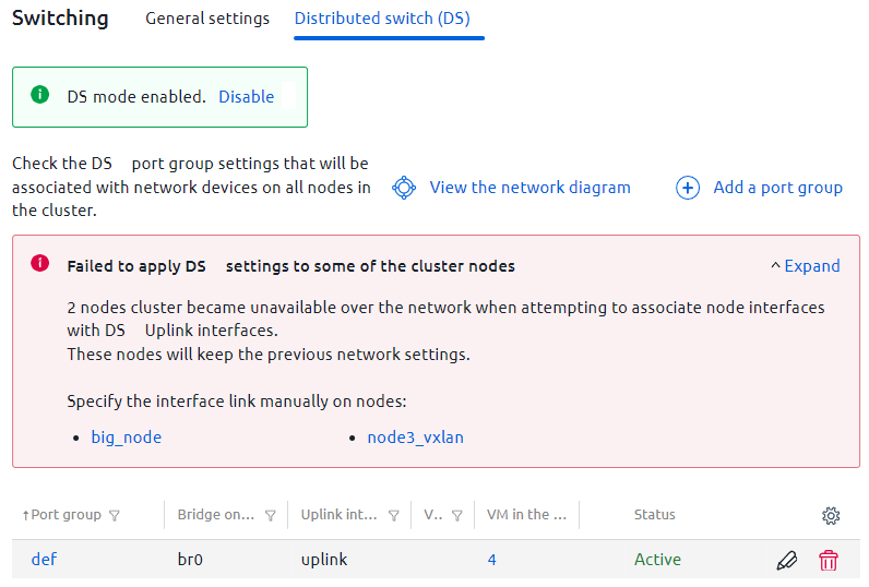
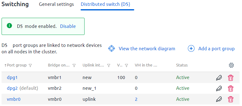
In the port group table, the bridge names on the nodes correspond to the bridge names in the network device card: enter Nodes → double-click the required node → Network settings.
If there are VMs in port groups, the table will display their number. Click the value in the "VMs in port groups" column to display the VMs in a port group.
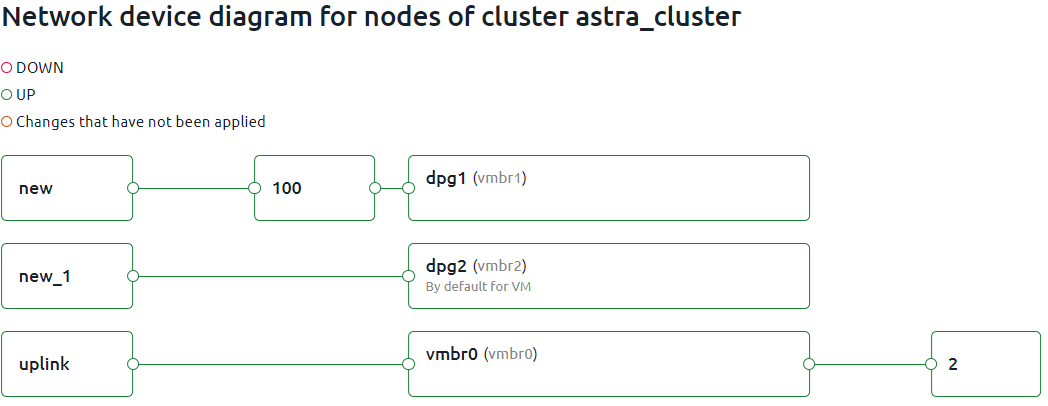
To view the network device diagram for the cluster nodes, click View the network diagram.
Deleting a template
To delete a port group from the DS, click  for the required port group.
Port group deletion will not be available if:
- there is a VM in it. Delete the VM from the port group, then delete the port group;
- the Use for new VMs by default option is enabled for it. Before deleting a port group, assign the "default" status to another port group.
Applying DS settings to a node
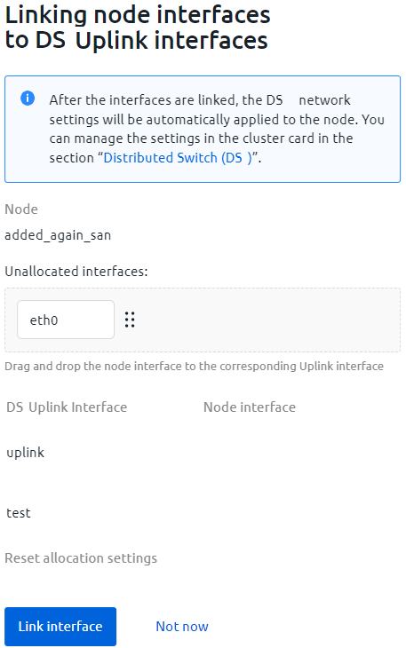
To link node interfaces with DS uplink interfaces:
- Enter Nodes → double-click the required node → Network settings → click Link interfaces to DS.
- In the panel that opens, drag the required node interface to the DS uplink interface.
- Click Link interfaces.
Example of setup
There is a cluster with two nodes. On each of these nodes, three bridges must be created according to the following conditions:
- first bridge — a network bridge with Internet access;
- second bridge — access of accounting VMs to the internal CRM installation;
- third bridge — access to internal resources only.
The following conditions and restrictions apply to the nodes:
- Internet access is provided through the eth0 interface;
- node 1:
- access to the internal installation is provided through the eth2 interface;
- access to internal resources is provided through the eth1 interface;
- node 2:
- access to the internal installation is provided through the eth1 interface;
- access to internal resources is provided via bond0.
To set up such a scheme, it is necessary to create three port groups, each of which has its own uplink interface:
- dpg1 — on both nodes, the uplink interface is linked to eth0;
- dpg2 — the uplink interface is linked to eth2 on node 1, and to eth1 on node 2;
- dpg3 — the uplink interface is linked to eth1 on node 1, and to bond0 on node 2.
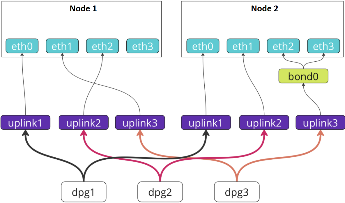
Once the cluster-level configuration is complete, a uniform network bridging configuration will be created, even though the interfaces for accessing certain resources are different on the two nodes.
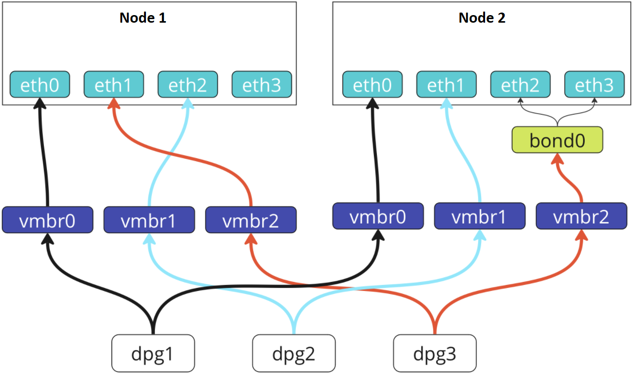
Fine-tuning of interfaces when automatically selecting a node is now available on the VM creation form. Without DS, it is only possible to arrange this by selecting a specific node. This way, you can create a VM, for example, with access to the Internet and access to CRM installation, or a VM with access to internal resources only.
 En
En
 Es
Es